¶ Create a Virtual Machine
In addition to the instructions provided here, at any time you can also refer to Google's instructions on Create a VM instance from a public image.
¶ Pre-requisites
The recommended machine type and specification for the VM are provided below:
|
Machine Type |
CPU |
Memory |
Disk |
|---|---|---|---|
|
N1 (n1-standard-1) |
1 vCPU |
3.75 GB |
30 GB |
- Private/LAN Subnet: You will need to specify the subnet (Network Destination/ Trust path) when deploying the cyber gateway in the next steps. For example, if you just like to give remote Zero Trust access to the subnet that the cyber gateway is on, your subnet in /24 format will be
192.168.68.0/24.- If it is green field deployment and no private resource subnets are present, create a new subnet
Make sure LAN subnet is different than the subnet configured for primary/WAN interface for Internet access. In example below, WAN subnet is 10.160.0.0/20 and LAN subnet is 192.168.68.0/24
- Reserve the IP address for CGW VM's LAN interface
- On GCP dashboard top search bar, search for VPC networks and click on it

- Select IP addresses from left panel
- Click on RESERVE INTERNAL STATIC IP ADDRESS
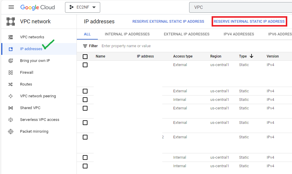
- Specify Name, mention small description for future identification
- Select Network or VPC
- Select Subnetwork or subnet
- Select Let me choose option in Static IP address drop down list
- Specify Custom IP address
Recommended: Reserve fourth IP address starting from the last IP of the LAN/private subnet for CGW LAN interface. For example, if LAN/private subnet is 192.168.68.0/24, then reserve 192.168.68.251 IP address for CGW LAN interface. See more examples in the Table below.
|
LAN subnet |
Recommended CGW LAN interface IP address |
Last IP of the subnet ending in |
|---|---|---|
| /23 | x.y.z.251 | 255 |
| /24 | x.y.z.251 | 255 |
| /25 | x.y.z.123 | 127 |
| /26 | x.y.z.59 | 63 |
- Click on RESERVE
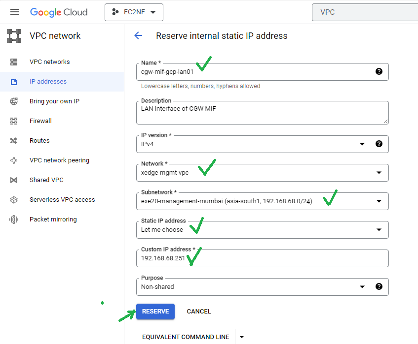
- In the Google Cloud console, go to the VM instances page, Go to VM instances
- Select your project and click Continue.
- Click Create instance.
- Specify a Name for your VM. For more information, see Resource naming convention.
- Select region
- Specify the Machine Type, recommended: N1 (n1-standard-1)
Optional: Change the Zone for this VM. Compute Engine randomizes the list of zones within each region to encourage use across multiple zones.
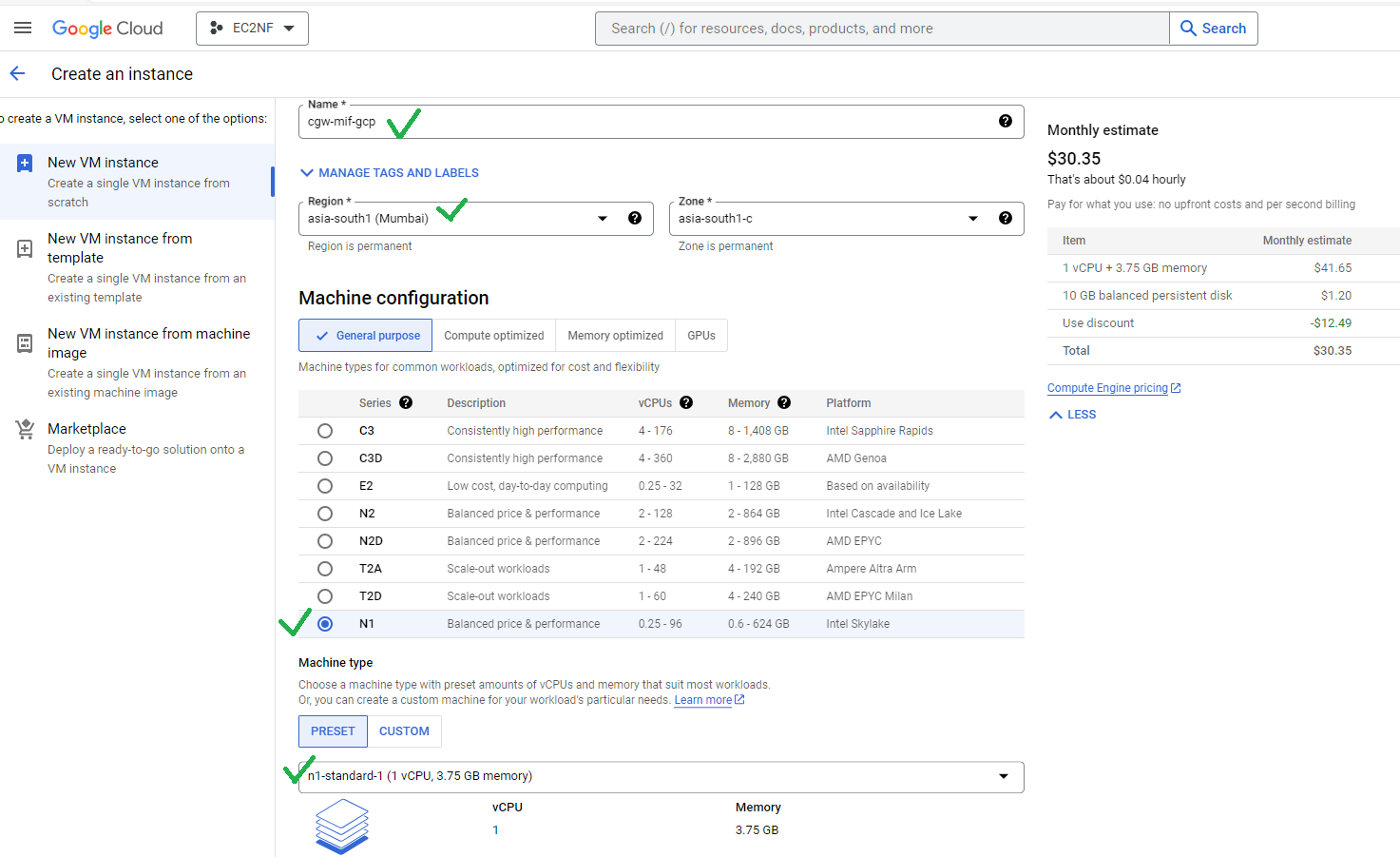
- Change Boot Disk

- Specify Boot Disk, leave selection to “PUBLIC IMAGES”
- Select operating system “ubuntu”
- Select version 22.04 LTS
- You can leave boot disk type to the default (Balanced persistent disk)
- Specify Size, (recommended 30 GB)
- Click on Create
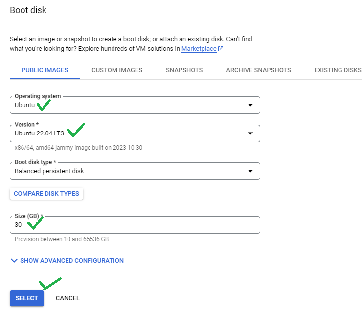
- Click on Advanced Options, to configure networking parameters
- Click on ADD A NETWORK INTERFACE
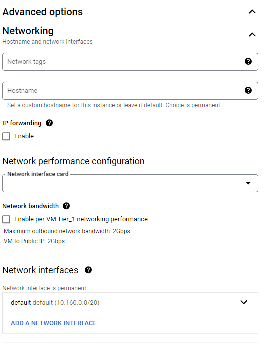
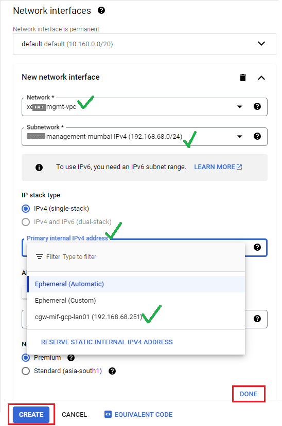
- Select network for primary interface which provides WAN connectivity
- Select Network/VPC from drop down list which is being used to deploy CGW VM on GCP
- Select Subnetwork/Subnet from drop down list. It must be LAN or private subnet which you want to access remotely. In previous steps same subnet was used to reserve .251 IP address for CGW LAN interface.
- Select Primary internal IPv4 address from drop down list. List will show name of the reserved IP.
- Click on DONE
- Click on CREATE, to create instance
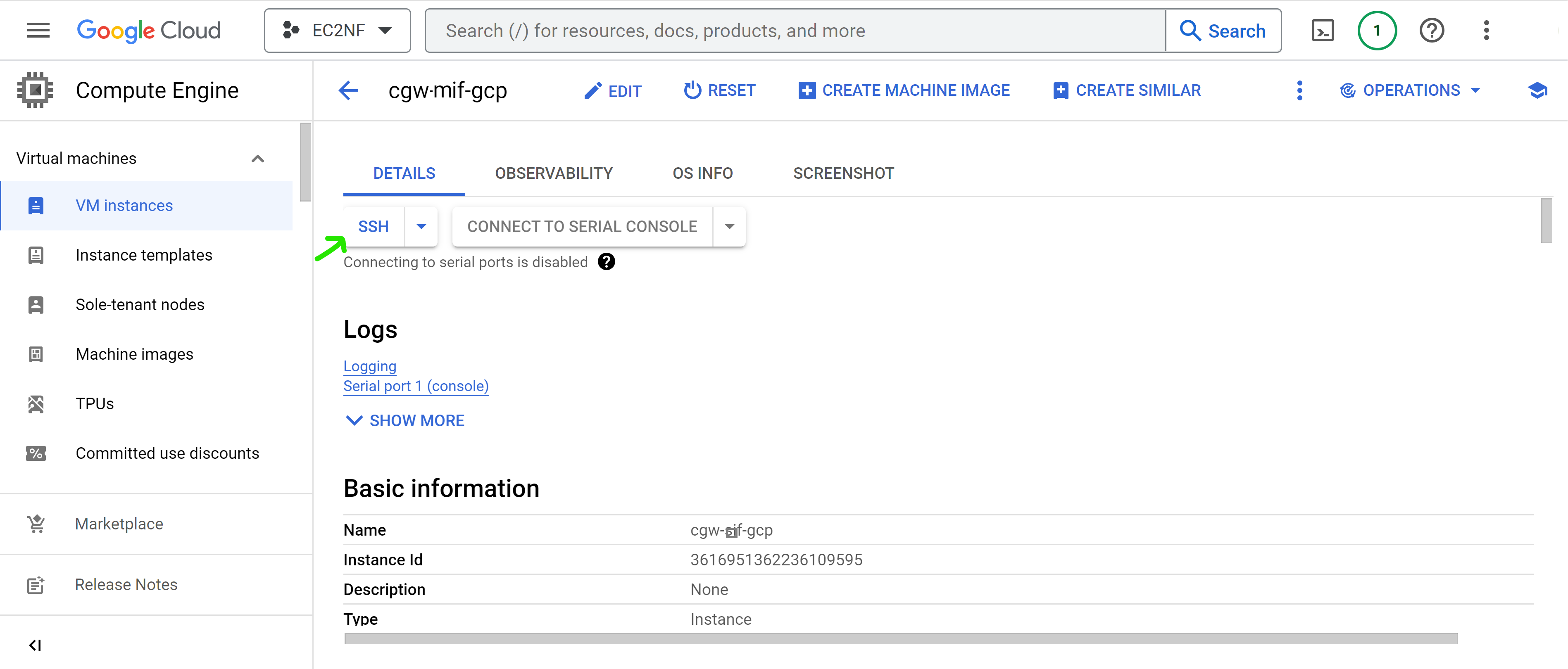
- Go to VM Instances page to view the state of CGW VM
- Click on the CGW VM name to view details of the VM

- Select SSH (in browser SSH is fine, you should be able to copy/ paste the cyber gateway deployment commands in the browser SSH shell)
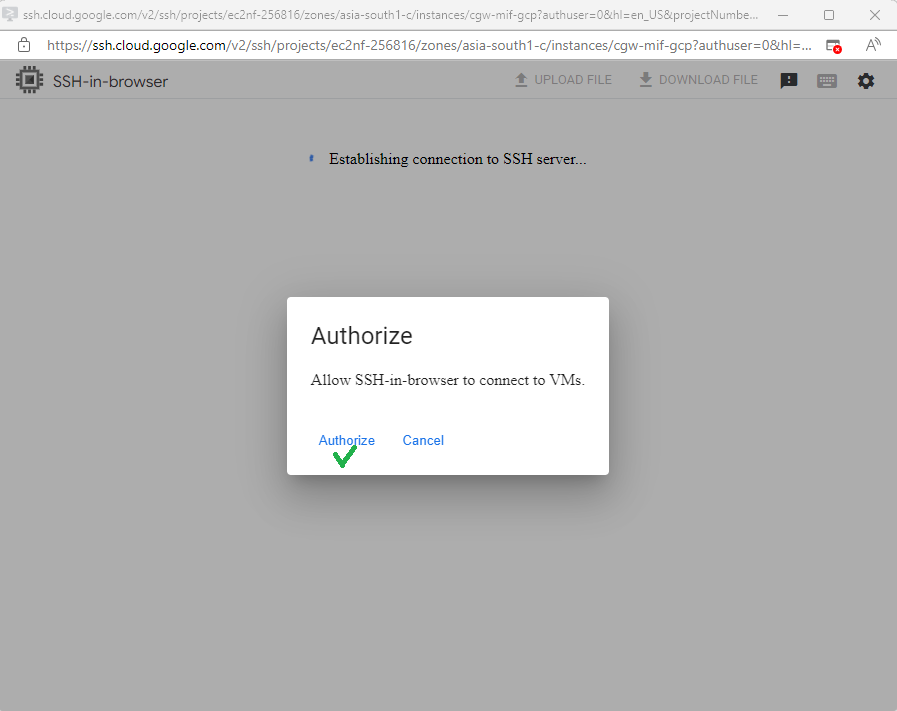
- Authorize ssh access from browser
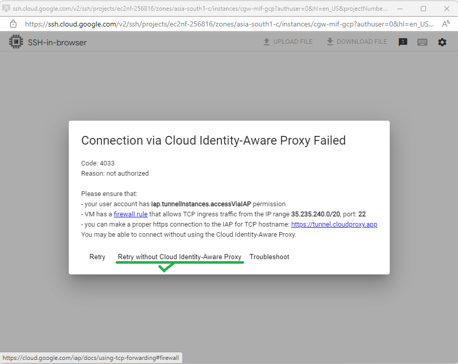
- If access/authorization fails, click on Retry without Cloud Identify-Aware Proxy option
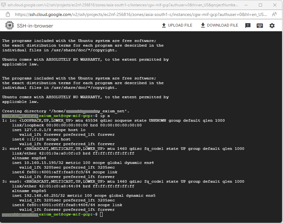
- After SSH is successful, VM console will be displayed
¶ Create a Cyber Gateway
To create a Multi Interface Cyber Gateway (CGW-MIF), follow the steps below.
- Navigate to the MSP admin console -> Client Workspace
- Click on Gateways in the left menu bar → Add Gateway
- Name - You may change the name of the CGW
- Select Gateway Type as Multi Interface. Fill in the details and add Gateway.
- High Availability (HA) - Please select ‘Yes’ if CGW to be deployed in High Availability mode. 2 Ubuntu VMs or any other 2 quantity of recommended hardware needed for HA setup, Please refer HA user manual for more detailed instructions.
- Admin Notifications Email - Provide email ID which will receive alerts/notifications related to CGW
- LAN Configuration
- If NAT is not required on LAN network then select No for option NAT on LAN, else skip it
- LAN Subnet - Enter LAN subnet (for eg. 192.168.68.0/24). This will be added as Trustpath automatically to Gateway, so no need to add this as Trustpath again. VERY IMPORTANT: This is the subnet that will be behind the gateway (i.e. plugged into the LAN port of the gateway) that you want remote users to be able to access. This is NOT the subnet that the WAN port of the gateway is on. Machines on this subnet will be able to access internet via CGW, if they are configured with default gateway as CGW LAN IP.
- LAN IP - Specify IP address of the Gateway which will be used by the devices behind CGW in LAN subnet specified in above parameter. Configured LAN Gateway IP will be installed on the CGW machine, so make sure it is not conflicting in network or not installed on any other device statically. If HA (High Availability) is enabled, then do not use .251 and .252 IP addresses as LAN Gateway IP. These IP addresses will be installed on Primary and Secondary nodes respectively.
- Next HOP GW for LAN - Provide gateway for LAN traffic. It is required when LAN traffic has to send all traffic to an IP which handles communication with actual core LAN network.
- DHCP Configuration
- Select Yes, if DHCP IP assignment should happen from CGW on LAN network. Please refer DHCP user manual for more detailed instructions.
- If selected Yes, DHCP server will be started for LAN
- Specify Start Range and End Range
- Select Yes, if DHCP IP assignment should happen from CGW on LAN network. Please refer DHCP user manual for more detailed instructions.
- In case of Multiple LAN subnets, click on + symbol and add additional subnets, else SKIP it.
- Enable / Disable DHCP functionality individually on each LAN subnet and set their start and end range
- Enable / Disable DHCP for All LANs
- VLAN Configuration
- Select Yes if CGW needs to support VLAN network segments. Please refer VLAN user manual for more detailed instructions.
- If Yes is selected, please specify VLAN IDs and VLAN subnets.
- Specify VLAN Gateway IP
- Inter VLAN Communication - Select Yes, if inter VLAN communication should be allowed
- Enable/Disable DHCP IP allocation for all VLANs by selecting Yes/No for DHCP for All VLANs option
- You may also enable/disable DHCP IP allocation for individual VLAN by selecting Yes/No for DHCP option
- By default, VLAN DHCP function will use start range .2 to end range .250
- Select Yes if CGW needs to support VLAN network segments. Please refer VLAN user manual for more detailed instructions.
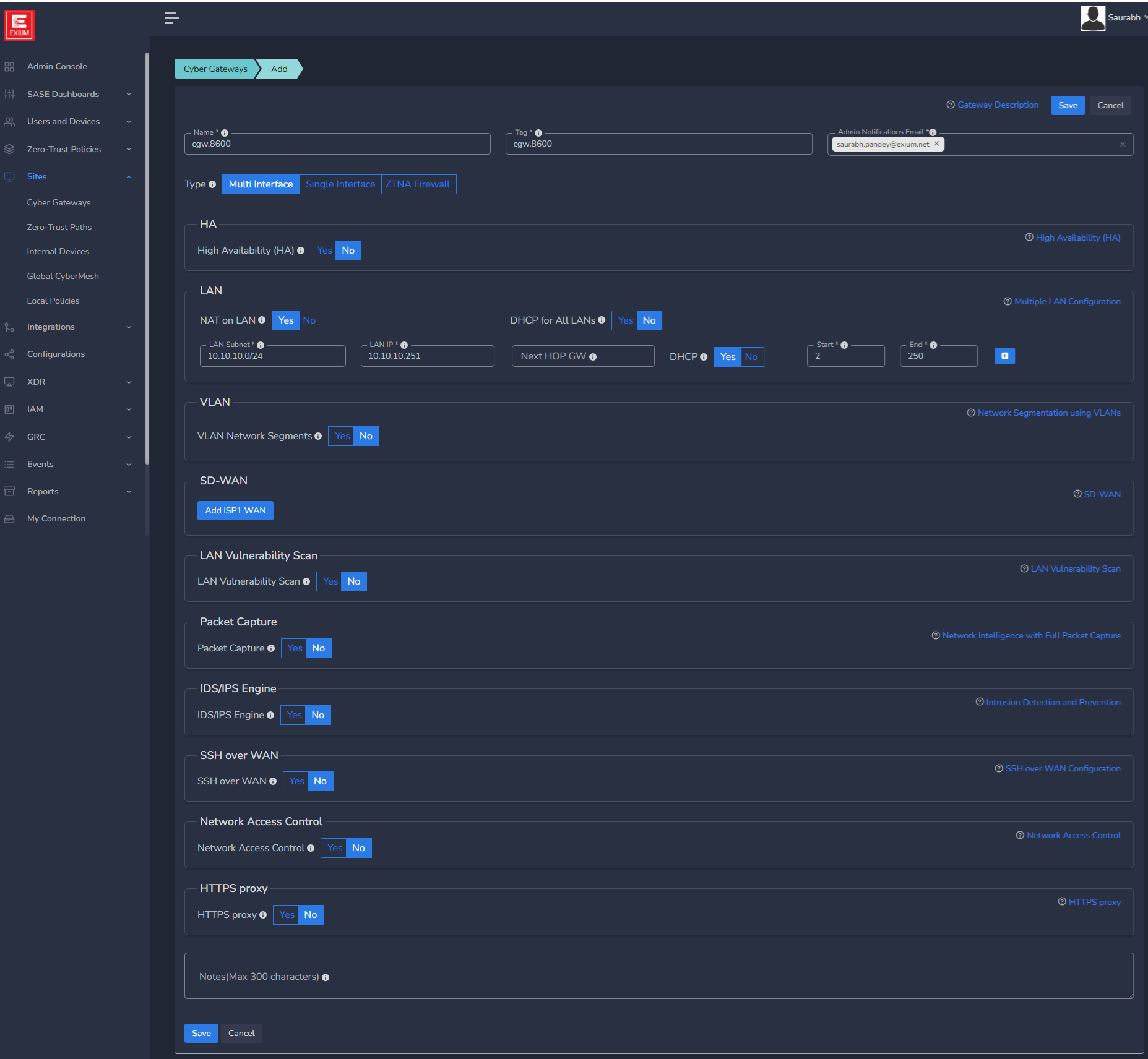
- SD-WAN Configuration
Mostly for CGW deployment on public clouds, you may not need static IPs on WAN interfaces but for specific requirements, it can be added.
- Static IP address along with their default gateway can be configured.
- Mostly it is required when existing Firewalls are replaced with CGW and ISP provided public IP and gateway need to configured on CGW node directly on WAN interface. Please refer SD-WAN user manual for more detailed instructions.
- Click on Add ISP1 WAN

- If WAN1 Static IP is set to Yes, configure below parameters, else skip it.
- WAN1 IP (Primary) - Specify IP with subnet for Primary CGW node
- WAN1 Gateway (Primary) - Specify gateway IP without subnet for Primary CGW node

- In case you want to deploy CGW with 2 WAN (WAN1 on ISP1 and WAN2 on ISP2) interfaces then click on Add ISP2 WAN, else skip it
- If selected Yes, you can select Traffic Distribution as Failover or Load Balance
- In case of Failover, only one WAN interface / ISP connection will be active
- In case of Load Balance, both WAN interfaces / ISP connections will be active and in load balance mode
- If Multi WAN is selected with WAN Static IP option, then WAN2 IP (Primary) must be configured with WAN2 gateway (Primary)
- Please refer SD-WAN user manual for more detailed instructions.

You can configure static IP on WAN1 which is on ISP1 and select No option for WAN2 which is on ISP2 in case ISP2 works on DHCP. In this case, WAN1 will have static IP and WAN2 will get IP allocated from ISP2.
- In case High Availability is enabled, static WAN IP and gateway are required for both nodes
- WAN IP (Standby) - Specify IP with subnet for Secondary CGW node
- WAN Gateway (Standby) - Specify gateway IP without subnet for Secondary CGW node

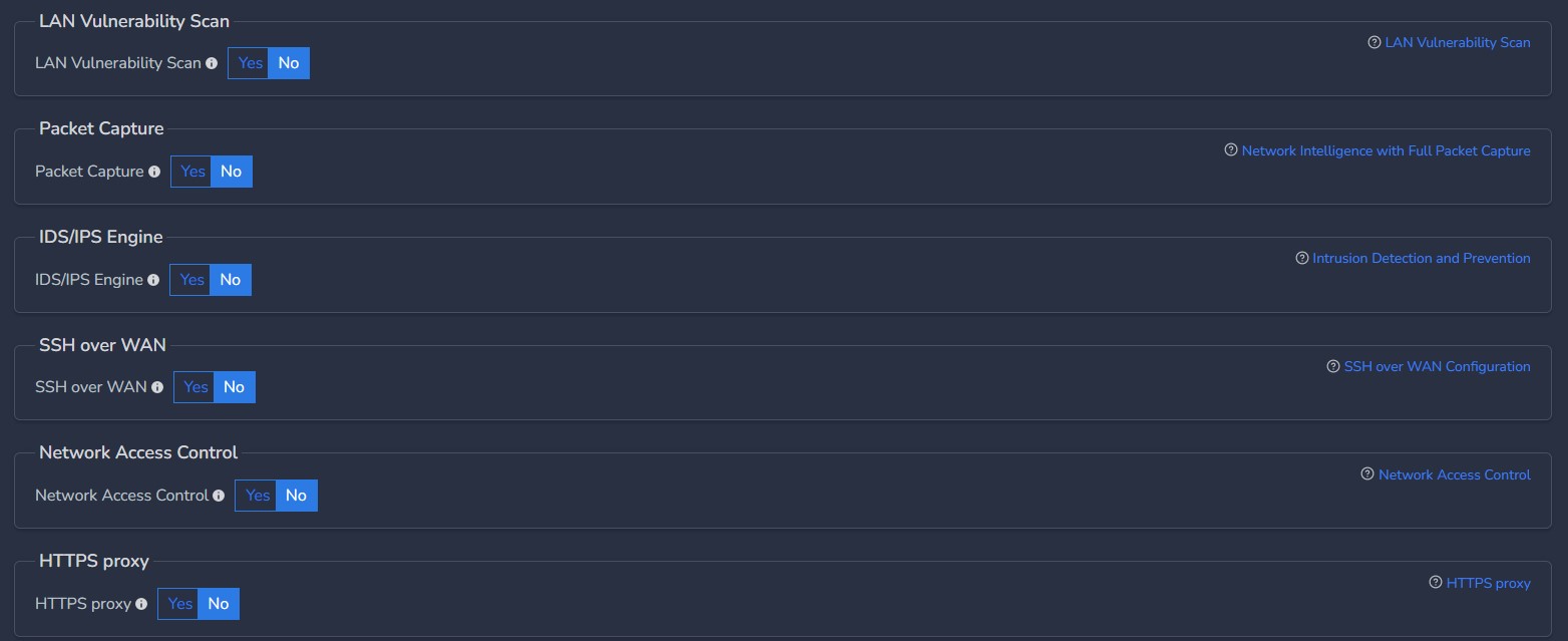
- As per requirements, customer can enable/disable advanced configuration mentioned below.
- Please refer user guides for advanced features for more detailed explanation
¶ Deploy the Cyber Gateway
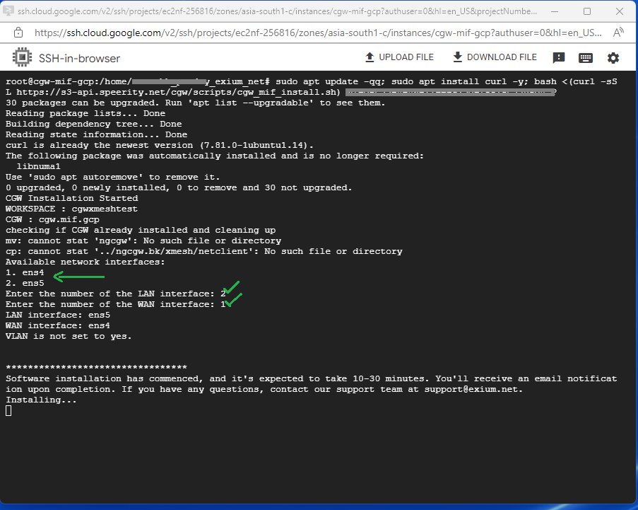
- Copy the Script for the cyber gateway you just created as shown in the screenshot below
- Paste the Script in the VM SSH console
- Press Enter
In case, you are unable to login to machine using SSH to copy and run CGW install command, then we recommend you to run pre-install script mentioned below. You have to type it on console, because copy paste won't work on some direct machine consoles.
bash <(curl -s https://s3-api.speerity.net/cgw/scripts/cgwctl.sh)Copy
Please share Workspace and CGW names with us on support@exium.net. We will push installation remotely.
The Cyber gateway deployment will start. At this time, you can leave the deployment running unattended. You will receive an email on the admin email that you specified earlier when the deployment is complete. You can also check the status of the cyber gateway in the Exium admin console. When cyber gateway is deployed successfully and connected, you will see a Green Connected Status as in the screenshot below.

- Select LAN and WAN interfaces after execution of install command on VM console:
- The Cyber gateway deployment will start. At this time, you can leave the deployment running unattended. You will receive an email on the admin email that you specified earlier when the deployment is complete. You can also check the status of the cyber gateway in the Exium admin console. When cyber gateway is deployed successfully and connected, you will see a Green Connected Status as in the screenshot below.
Once the cyber gateway is deployed successfully and connected, you can start testing the Zero Trust Secure Private Access policies.